Do you know why lithium-ion batteries need a Battery Management System (BMS)?
Below is a complete explanation of how a BMS works.
As high-performance electrochemical energy storage carriers, lithium-ion batteries (rechargeable) are highly sensitive to voltage, current, and temperature during charging and discharging, due to their material composition and working principles. To ensure system safety, extend cycle life, and maintain consistency, a Battery Management System (BMS) is essential for real-time monitoring and intelligent control.
Lithium-ion batteries exhibit the following key characteristics during electrochemical reactions:
-
Overcharging can easily lead to structural damage to the cathode material and decomposition of the electrolyte;
-
Over-discharging can cause dissolution of the anode copper current collector, resulting in permanent battery damage;
-
Overcurrent and short circuits may trigger thermal runaway, posing safety risks;
-
Charging/discharging at excessively high temperatures accelerates material aging, while low temperatures reduce ionic conductivity.
In UNIWEALTH’s energy storage solutions, we employ a self-developed BMS that not only fulfills the basic protection functions mentioned above but also integrates:
-
Multi-level thermal management coordination: Combined with liquid cooling/air cooling systems to achieve closed-loop temperature control;
-
Fault self-recovery mechanism: Some abnormal states can be automatically reset once conditions return to normal, improving system availability;
-
Full life-cycle data tracking: Supports battery performance degradation analysis and predictive maintenance.
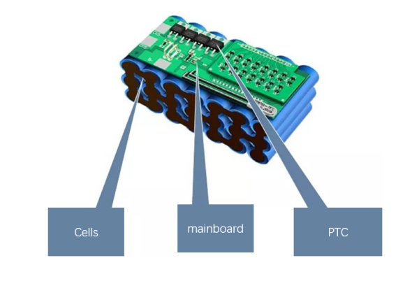
Through the triple protection architecture of “BMS + PTC + system thermal management,” UNIWEALTH ensures that lithium-ion batteries operate safely, efficiently, and with long lifespan under various complex operating conditions, providing users with a reliable and stable energy storage foundation.
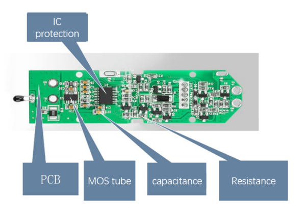
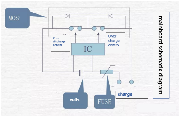
The Battery Management System (BMS) includes a control integrated circuit (IC), MOS switches, and auxiliary components such as NTC ID memory. Under normal conditions, the control IC keeps the MOS switches turned on, allowing the battery to communicate with the external circuit. When the battery voltage or circuit current exceeds the set values, the control IC immediately turns off the MOS switches, thereby protecting the battery.
Building Management System Exterior
Negative Temperature Coefficient (NTC). When the ambient temperature rises, the resistance value decreases. Electrical or charging equipment in use will respond to an internal interrupt and stop charging/discharging.
Identification (ID) is divided into two types: one is the memory ID, which typically uses a single-wire interface and is used to store information such as battery type and production date; the other is the resistor ID. Both can be used for product traceability and application restrictions.
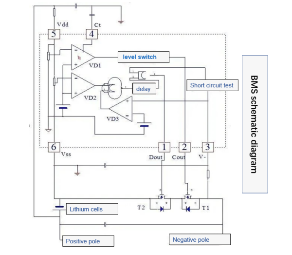
During battery charging, if the voltage exceeds the set value Vc (4.25–4.35V), VD1 flips COUT to a low level, T1 turns off, and charging stops. When the battery voltage falls back to VCR (3.8–4.1V), COUT becomes high level, and T1 resumes charging. At this point, VCR is lower than the constant value VC to prevent frequent current switching.
Overdischarge Protection
When the battery voltage drops to the set value VD (2.3–2.5V) due to discharging, VD2 flips. After a brief delay locked internally by the IC, DOUT becomes low level, T2 stops, and discharging stops.
Overcurrent and Short Circuit Protection
When the discharge current of the circuit exceeds the set value or the output is short-circuited, the overcurrent/short circuit detection circuit turns off the MOS transistor and cuts off the current.
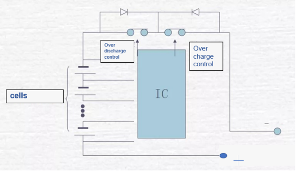
Similar to a single cell, in a multi-cell protection circuit, the BMS can also provide overcharge, overdischarge, overcurrent, and short circuit protection for the batteries.
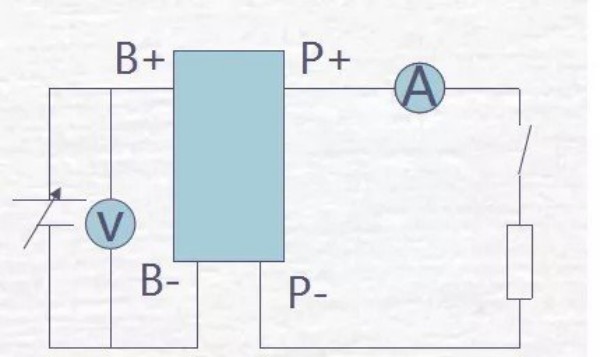
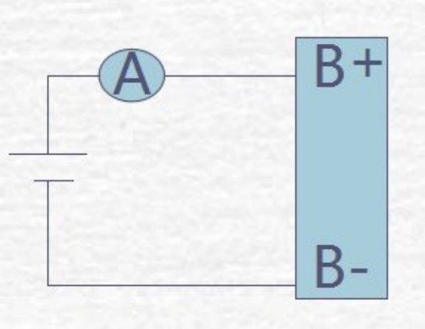
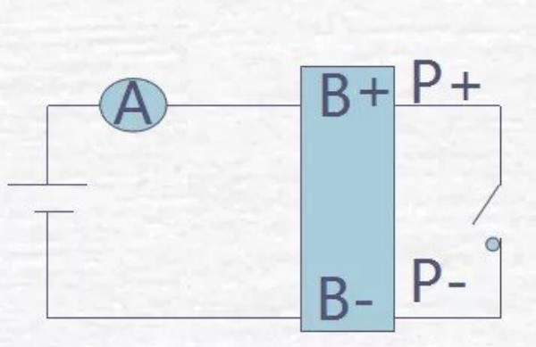
Power Consumption Test Schematic Diagram
Short Circuit Test Schematic Diagram
Overdischarge Test Schematic Diagram